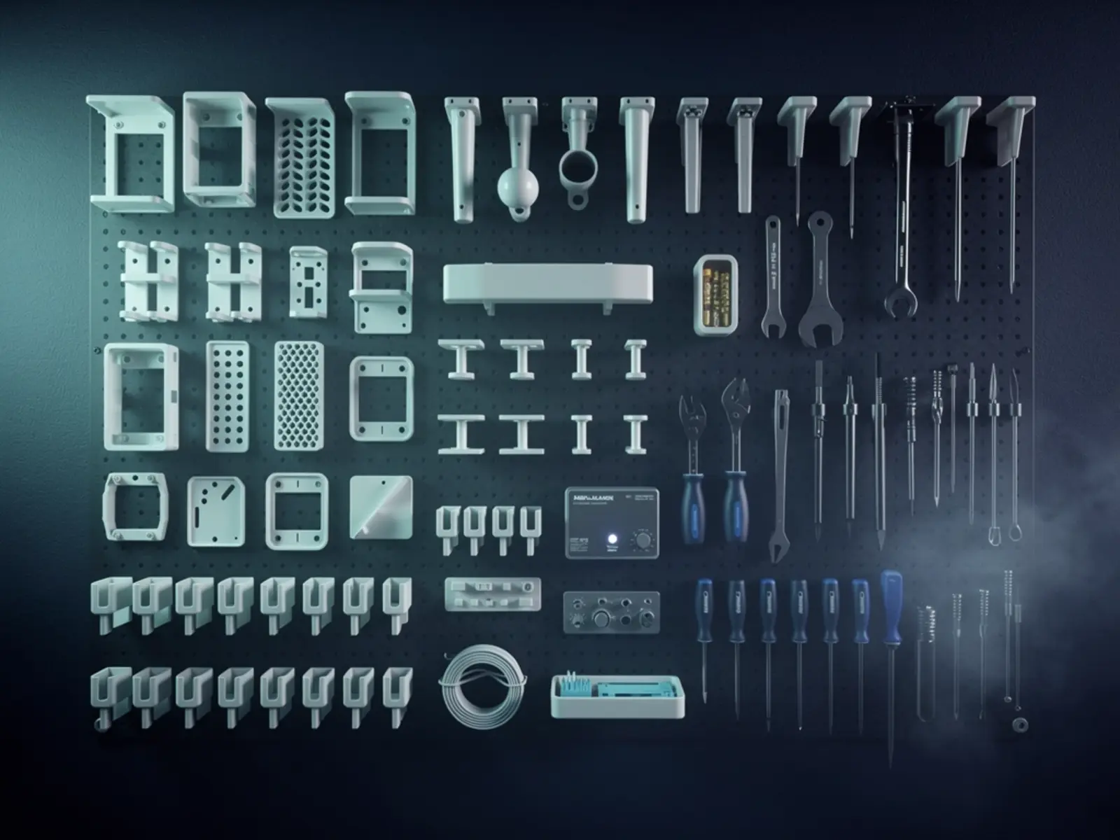
The idea
Create a reusable enclosure and mounting family that makes APX prototypes easier to assemble, cool, repair and reproduce. V1 covers one Raspberry Pi-class board and one ESP development board using a shared fastener convention, labelled connectors and replaceable mounting plates. It is a small tested library rather than a catalogue of unverified models.
The connection
A shared fabrication language turns one-off prototypes into serviceable products. Carriers, fasteners, mounts and enclosures become reusable design knowledge.
How it could work
Separate the electronics carrier, outer shell and mounting interface. This allows one carrier to be used in a desktop enclosure or wall bracket without redrawing the board mounts. Use dimensions taken from the actual board revision and connector bodies; a nominal board outline omits cable plugs, insertion space and component height.
Use screws and replaceable inserts for frequently opened prototypes. Snap fits can be useful, but depend on material, print orientation and repeated flexing. Print clearance and insert coupons before committing to a full enclosure. PETG, ASA and other materials need selection based on heat, environment and fabrication capability rather than a universal material rule.
What would prove it
Build two copies of each enclosure on separate print runs. Fit actual boards and cables, open and close them 20 times, then run a representative workload for two hours while logging board temperature. Compare against the unenclosed baseline. Perform a documented gentle cable-pull and mounting-load test appropriate to the intended installation.
Proposed gate: all four assemblies fit without filing; connectors are usable without removing the board; no insert spins during 20 service cycles; temperatures remain within the board's specification; the mount carries its declared test load without damage. A workshop test does not establish an ingress or fire rating.
The path to a complete build
- Inventory the exact two boards and define common fasteners and mounting interfaces.
- Print dimensional, insert and snap-fit coupons; record the selected clearances.
- Build the carrier and serviceable shell, then test fit with real cables.
- Run thermal and service-cycle tests; change venting before refining cosmetics.
- Release CAD, exports, print profile, BOM, labelled assembly photographs and the compatibility matrix together.
Open the engineering notebook
Components, interfaces and calculations
For each supported board, record mounting-hole coordinates, standoff height, connector keep-outs, airflow needs and accessible service points. Publish those in a dimensioned drawing alongside the native CAD and neutral export. Choose a small set of fasteners and insert sizes, then document them without relying on an ambiguous generic screw bag.
Measure the machine's hole and slot errors with a coupon. Build a tolerance stack for board-to-port alignment: printer error, board placement, wall thickness and connector clearance all contribute. Keep vents and strain relief replaceable so revisions do not require replacing the whole housing.
Scope and development questions
Allow 4–6 sessions for two validated enclosures. Cost material by measured part mass and include print failures, inserts and assembly time. Hybrid CNC or laser-cut panels should be a later variant of the same dimensional interface. Resolve indoor/outdoor use, mounting loads and board revisions before claiming compatibility. The first useful library is small enough that every model has actually been built.