The idea
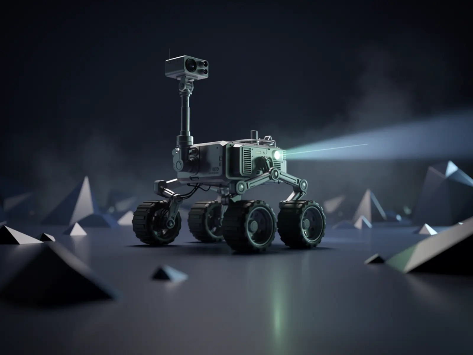
Build a small indoor wheeled platform that can be driven predictably, stop when its operator disappears and produce useful sensor logs. V1 is a two-wheel differential-drive rover with a caster, wheel encoders and a front distance sensor. Video and AI can run on a phone or external computer later; they are not prerequisites for reliable motion.
The connection
A reliable movement platform makes later sensing and intelligence experiments meaningful. The mechanical and control foundations come before claims of autonomy.
How it could work
Separate the command interface from the motor-control loop. Commands carry a sequence number and expire locally. The ESP32 owns speed limiting, watchdog handling and a deliberate arm state. After reboot or reconnection it starts stationary. Use wheel feedback to distinguish commanded motion from actual motion; timed open-loop drive is useful for bring-up but will drift with battery voltage and floor friction.
Choose the motor driver using the motors' stall current and the board's thermal capability, not just its headline peak current. Separate motor power routing from logic power and test voltage dips at starts and reversals. The DRV8833 is a candidate for small compatible motors, not a universal selection.
What would prove it
Use a marked indoor course with a one-metre straight and a turn. First test on blocks, then at a low speed on the floor. Run 20 disconnect trials while moving and 10 trials each for boot, application crash and command replay. Then complete five one-metre runs and record lateral error, distance error and supply voltage.
Proposed gates: new commands expire within a chosen 300 ms timeout; motion stops within a measured 100 mm at a 0.2 m/s test speed; no automatic restart after reconnect; five runs finish within 100 mm of the target after calibration. These are development targets, not certified collision protection.
The path to a complete build
- Measure motor current and establish the safe driver/supply pairing.
- Implement DISARMED, ARMED and FAULT states plus command expiry.
- Calibrate encoders and verify wheel directions; add low-speed closed-loop control.
- Add ranging as a supplementary stop input; test dark, angled and narrow obstacles.
- Publish the wiring map, firmware revision, test CSV and a repeatable demonstration course.
Open the engineering notebook
Components, interfaces and calculations
Two encoder gearmotors, wheels, caster, ESP32 board, suitably rated dual H-bridge, protected battery assembly, matched charger, regulator, power switch and front ranging sensor form the core BOM. Add a removable electronics tray and keyed connectors. Keep the first chassis spacious enough to probe voltages and replace a motor.
Wheel distance per encoder count = wheel circumference / effective counts per wheel revolution. For track width b, angular velocity = (right wheel speed − left wheel speed) / b. Measure the loaded wheel diameter and effective track width before calibration. Treat odometry as an estimate; wheel slip breaks the model.
Scope and development questions
Allow 4–6 build sessions, plus calibration. Quote drive hardware, power system, control/sensors and printed material separately; keep a spare motor in the prototype budget. Resolve expected payload, floor types and runtime before selecting gearing. The decision to add an Android phone should follow a successful drive-and-stop test, with a new mass and power budget.