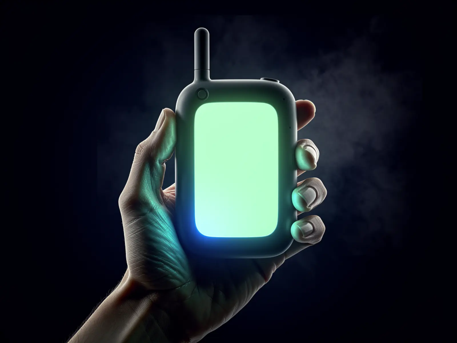
The idea
Build a portable instrument for one useful workflow: viewing GNSS position, recording a track and reviewing device/battery status. V1 is not a general-purpose smartphone replacement. Wi-Fi tools, messaging and other applications can follow once input, storage and power behave reliably.
The connection
The handheld combines embedded interface design, location sensing and enclosure work around a focused use case. Its value comes from doing that job well within real power and memory constraints.
How it could work
Start with an integrated ESP32-S3 display development board rather than a custom PCB. Verify that the display, GNSS, storage, USB and audio requirements fit the actual board's pin allocation and available memory. Maintain a pin/resource table covering boot-strapping pins, bus sharing, interrupts and power domains.
Choose the screen for sunlight readability and energy use, not diagonal alone. A four-inch display can dominate the energy budget. Separate sampling from UI updates, and write buffered records so slow storage does not freeze buttons. GNSS fixes must carry age and quality; show NO FIX instead of presenting the last coordinates as current.
What would prove it
Log a one-hour walk on a known route with several stops and one indoor segment. Save time, coordinates, fix quality and sequence numbers. Interrupt power during logging, fill the storage medium and disconnect GNSS. Use a USB power meter to compare screen-brightness and radio modes.
Proposed gate: the device clearly distinguishes valid, stale and absent fixes; an interrupted log remains readable up to the last committed block; full storage causes a visible error instead of silent loss; controls remain usable throughout logging. Compare position error against a known reference point and the chosen receiver specification rather than promising survey-grade accuracy.
The path to a complete build
- Define the one-screen workflow and a complete interface allocation.
- Bring up display, controls, GNSS and storage individually.
- Integrate logging with recovery, then measure energy in actual use.
- Validate antenna placement and ergonomics in a printed case.
- Consider a custom PCB only after the development-board prototype passes and connector locations are stable.
Open the engineering notebook
Components, interfaces and calculations
Core BOM: supported screen/controller board, GNSS module and antenna, buttons, microSD or suitable local storage, documented battery/charger/power path and a serviceable printed enclosure. Keep the antenna away from noisy power wiring and display electronics; verify performance in the final case.
Estimate runtime from measured modes: average power = sum(mode power × fraction of time). Runtime = usable battery Wh / average W. Record backlight level, GNSS state, radio use and conversion losses with every estimate. A battery's mAh rating cannot be compared directly to power at a different voltage.
Scope and development questions
Plan 5–8 sessions for the integrated-board version; PCB design and a board respin are separate allowances. Obtain quotes for the complete display board and power system before designing the enclosure. Resolve gloves, outdoor visibility, target runtime and whether audio is genuinely required. The release evidence is a usable log, measured runtime and a recovery demonstration.